
Low Power
Suitable for battery-powered card and tag designs; broadcast interval and battery life are optimized together.
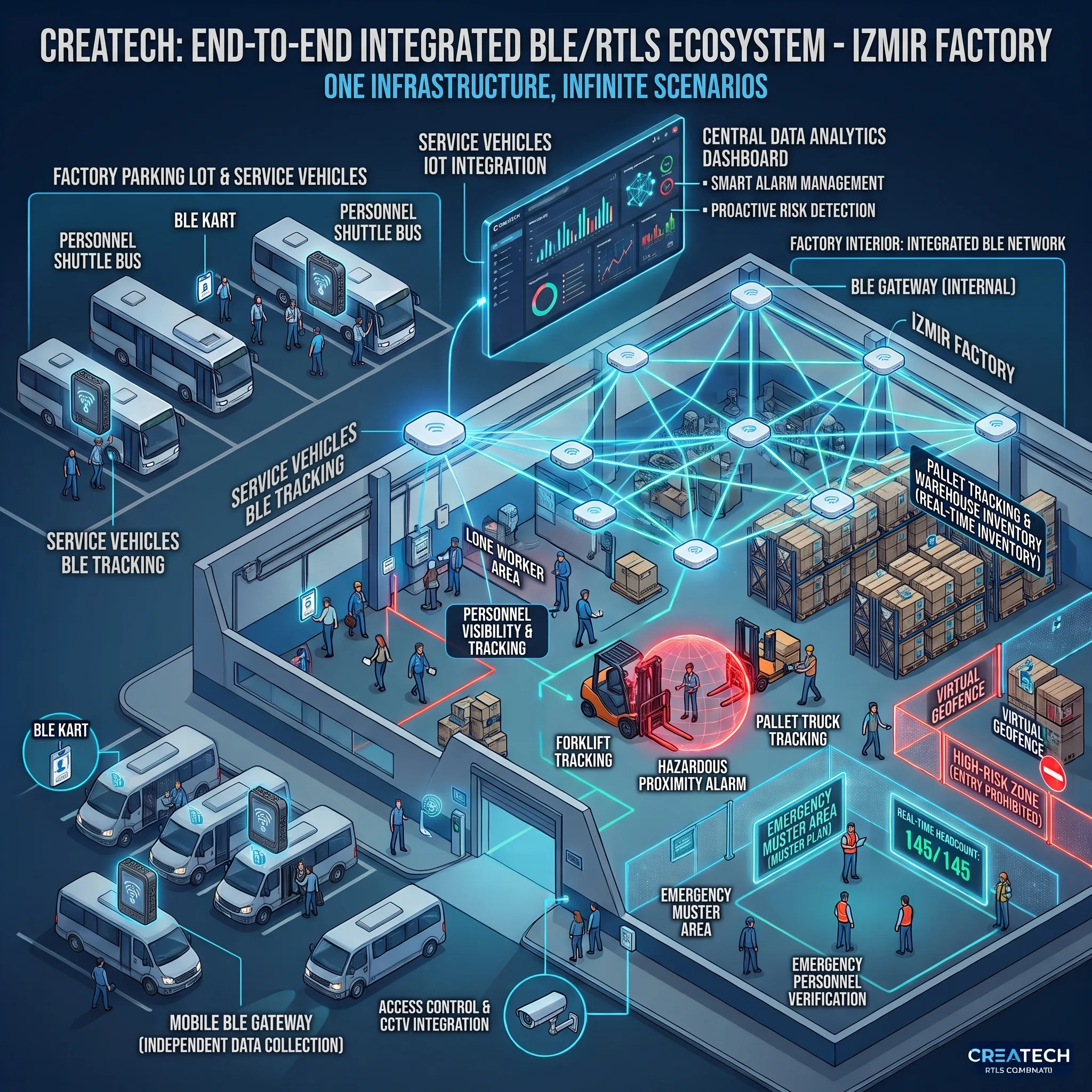
A real-time location infrastructure that brings people, forklifts, pallets, equipment and shuttle vehicles together in a single location and identity layer.
Economical zone detection with RSSI, precise X-Y positioning with AoA in critical areas and a second verification layer through CCTV and artificial intelligence all run on the same BLE network. Once the infrastructure is in place, new tag types and software modules are added to the same platform. This page covers the location layer of our industrial automation solutions in detail.
Integrated real-time location infrastructure for plants, warehouses, staff, forklifts, pallets and shuttle vehicles. One infrastructure, many uses, a scalable architecture.
BLE RTLS (Real-Time Location System) locates staff, vehicles, equipment and assets indoors in real time or near real time. Broadcasts from BLE cards and tags are picked up by Gateway or Locator devices in the field and turned into position data by the central RTLS engine.
RTLS is not a single staff-tracking application; it is a digital infrastructure on which different assets become visible over one network. New tag types and new software modules can be added to that same network later.
Four screens from the Createch BLE Monitor and BLE Setup interface: live monitoring, system definitions, an emergency drill and retrospective trace analysis. The images are from a simulation environment running on demo data.
Open the images full size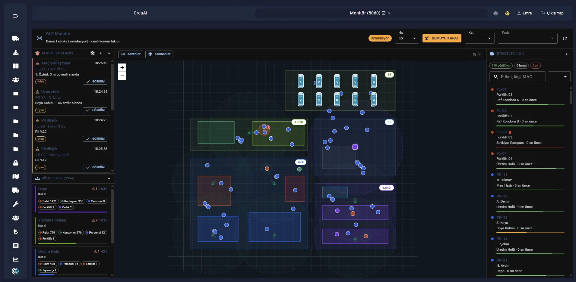
The live position of every tag on the site plan, together with gateway coverage areas. The left panel shows open alarms and per-zone counts; the right panel lists the tags and when each was last seen.
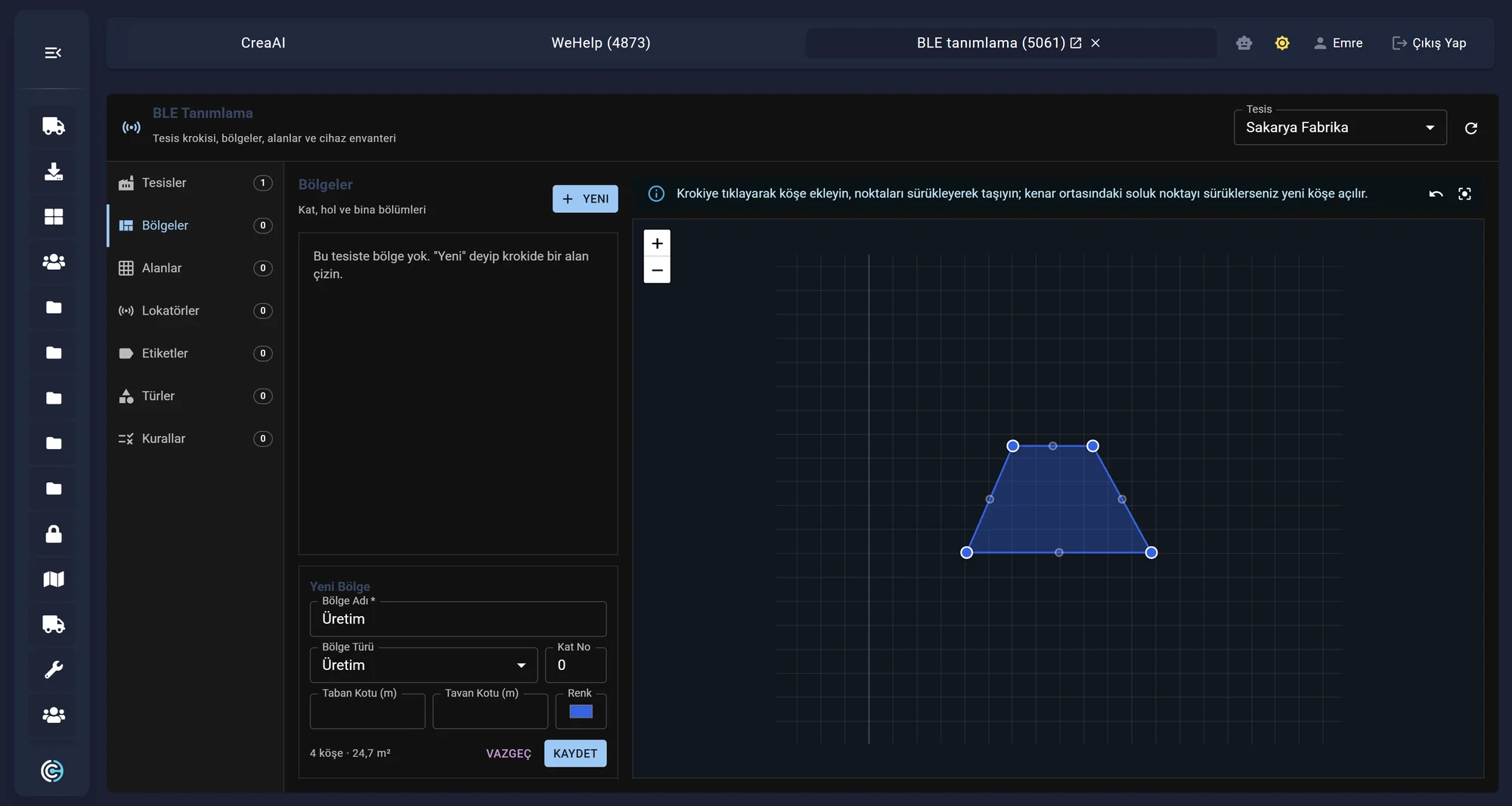
Zones are drawn on the site sketch and floor, zone type and level details are entered. Locator, tag, type and alarm rule definitions are all managed from the same screen.
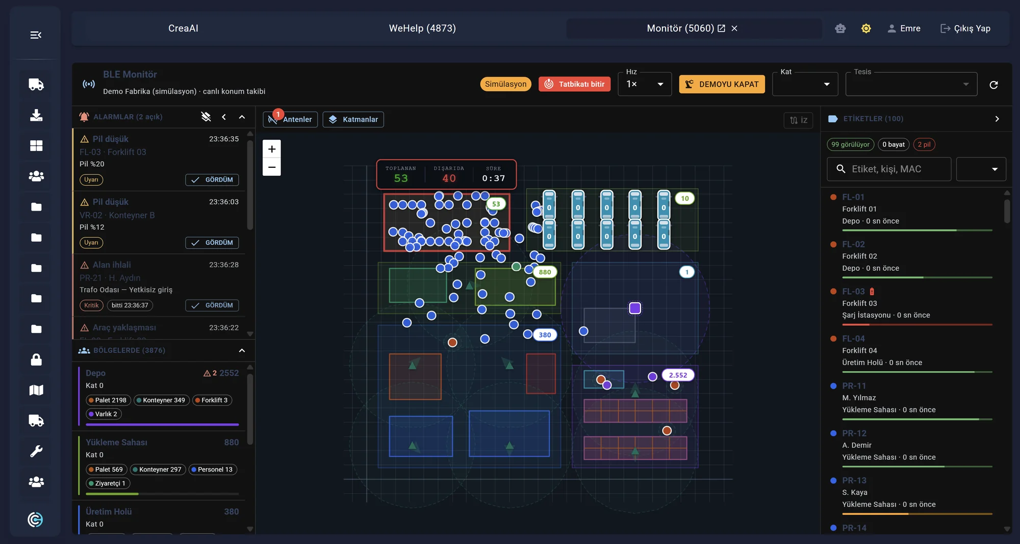
When an emergency or drill is started, the number of people who have reached the assembly area and the number still outside are tracked along with elapsed time. Low-battery and unauthorized-area alarms appear on the same screen.
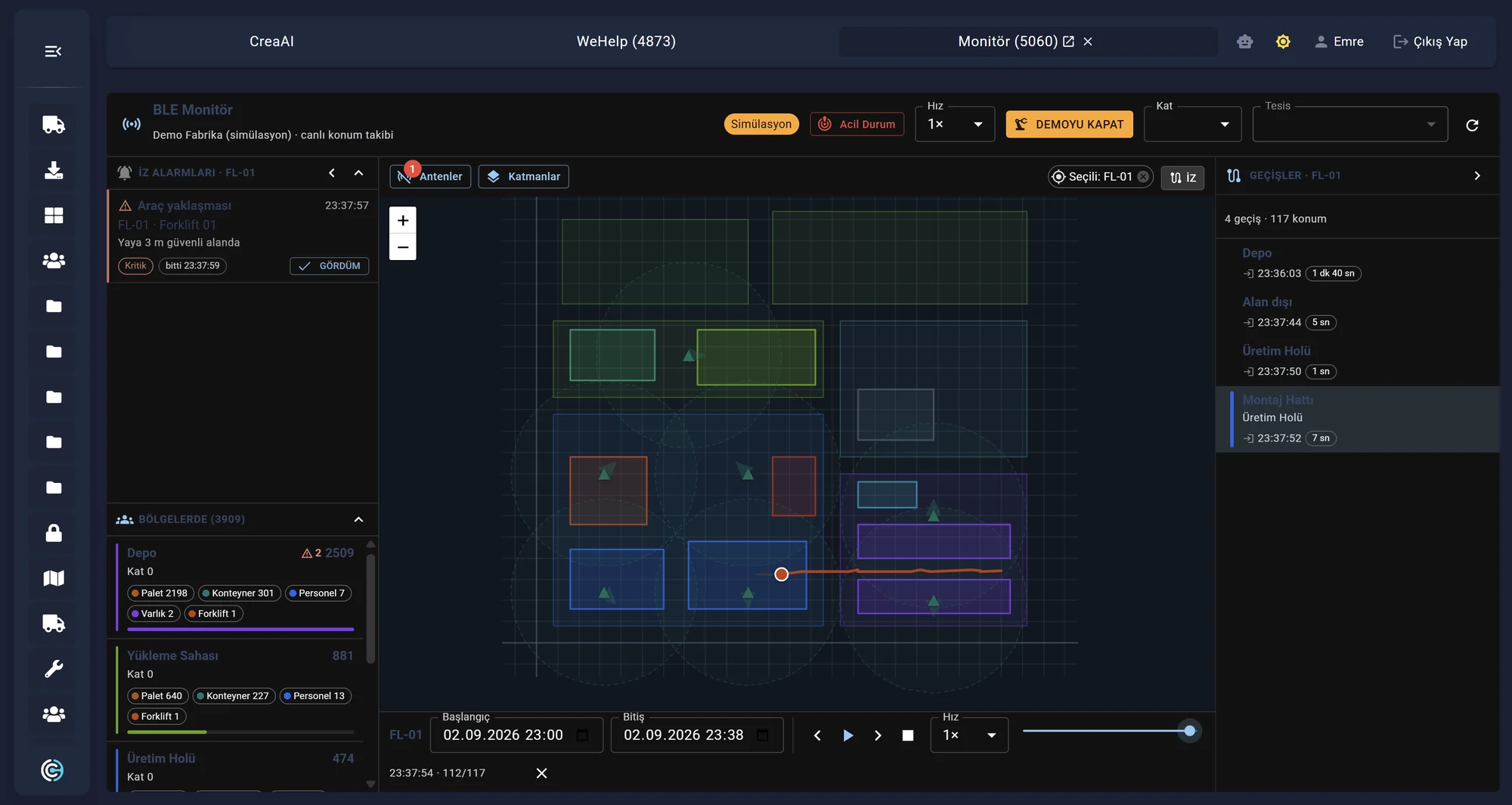
The trace of a selected tag over a chosen time range is drawn on the plan and played back and forth with the time bar. Zone crossings are listed with their durations, so post-incident review is done from the record.
The battery-powered broadcast unit carried by staff, forklifts, pallets and equipment.
Field devices receive the BLE broadcasts and relay them to the center.
The broadcasts are turned into position data by the central engine.
Position is shown on the map, and rule breaches raise an alarm.
What the location layer looks like in the field: live tracking of a moving vehicle, density distribution over a floor plan, and location data watched alongside camera footage. The images are from reference installations and validation rigs.

An autonomous vehicle running a reference course is picked up by ceiling-mounted BLE gateways and its position is marked on the digital plan in real time. Position accuracy and latency are measured on rigs like this.

A location cloud overlaid on the store plan shows how much time is spent in which aisles and zones. The same data can be used for layout planning, shift planning and measuring the impact of a campaign.

The positions of staff, patients and equipment are marked both on the floor plan and on the live camera image. The operator does not have to switch between screens to confirm an alarm: the location and video layers meet in one interface.
Suitable for battery-powered card and tag designs; broadcast interval and battery life are optimized together.
Zone detection and precise positioning can be used together in the same project: each area gets just as much technology as it needs.
The same BLE card can be used in the plant, on the shuttle vehicle and in other processes; the identity layer is never split.
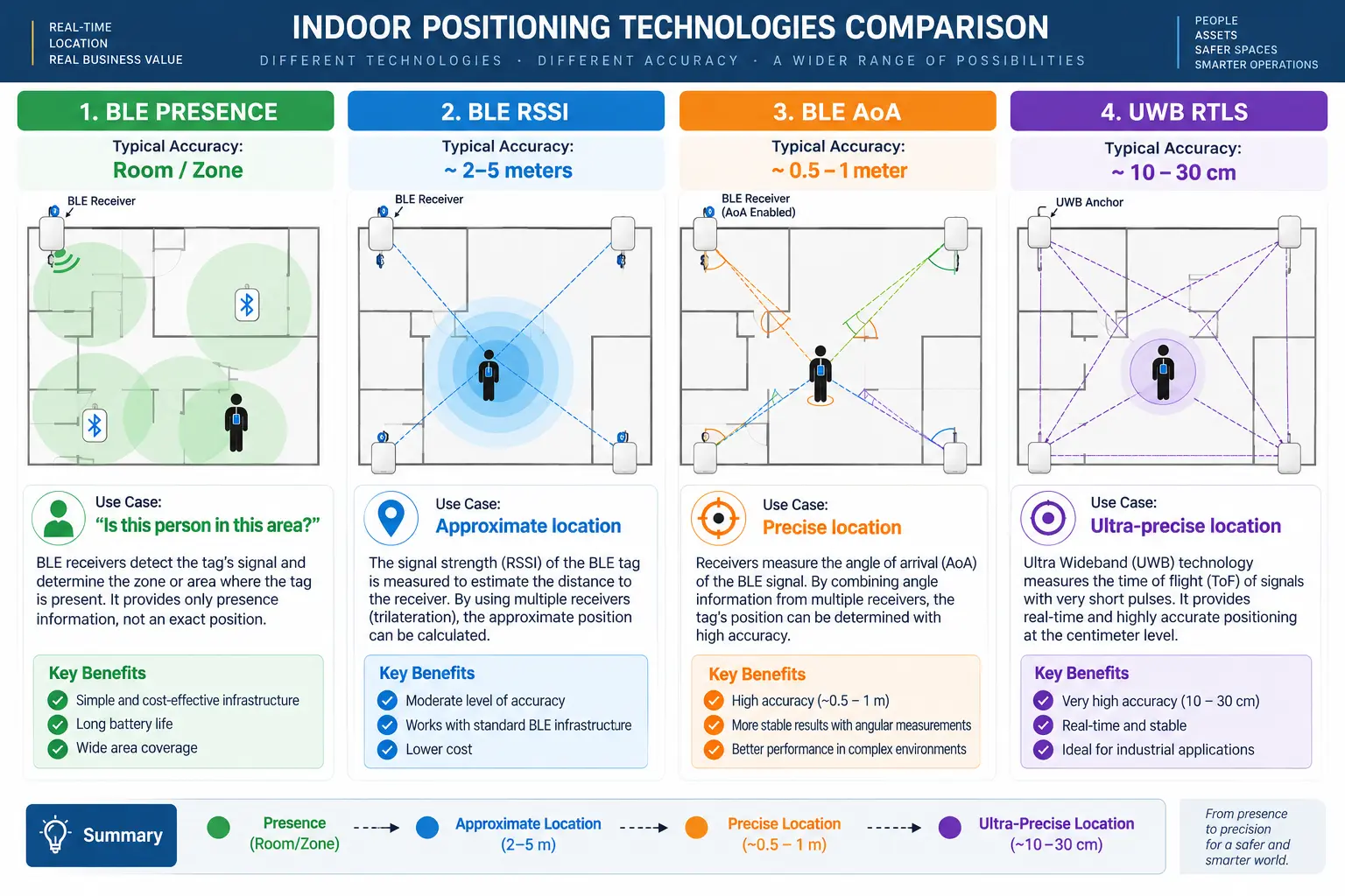
The RSSI-based approach answers “which section or zone?” economically. AoA measures the angle at which the signal arrives, allowing more precise X-Y positioning in critical areas.
That allows a hybrid architecture rather than fitting the whole plant with expensive AoA infrastructure.
The BLE RTLS & AoA introduction documents are available in English and Turkish. The overview summarises the solution in ten pages; the technical version covers the phase difference geometry, multi-locator estimation, site engineering criteria and the acceptance test items in detail.
The ten-page summary: the in-plant location layer, logistics and delivery, safety and artificial intelligence.
EN TechnicalThe detailed twenty-six-page version: AoA angle calculation, Locator geometry, site engineering and acceptance criteria.
TR GenelThe ten-page overview in Turkish, with the same layout and the same diagrams.
TR TeknikThe detailed twenty-six-page version in Turkish, with the same layout and the same diagrams.
Improves position accuracy by measuring the angle at which the BLE signal reaches the antenna array.
The antenna array on an AoA Locator analyses the phase differences a BLE Direction Finding signal produces across its antennas. Using I/Q samples, antenna geometry and positioning algorithms it calculates azimuth, and with suitable hardware and installation, elevation as well.
The angles measured by several Locators are assessed together to estimate the tag's position. This approach gives higher spatial accuracy than proximity information alone.
The Direction Finding signal (Constant Tone Extension) is broadcast.
The phase differences across the Locator antennas are detected.
Raw I/Q samples are processed together with the antenna geometry.
Azimuth — and with a suitable installation, elevation — is calculated.
| Technology | Measurement | Use Case |
|---|---|---|
| BLE RSSI | Signal strength | Zone / section detection |
| BLE AoA | Angle of arrival | Precise positioning |
| Channel Sounding | Distance | Next-generation precise ranging |
| UWB | Time / distance | Very high precision |
Using the right measurement technology in the right area raises the return on the investment.
Offices, canteen, general warehouse: RSSI zone detection gives sufficient accuracy economically.
Forklift routes, production and loading areas: precise X-Y positioning with AoA comes into play.
Shuttle vehicles: an in-vehicle BLE Gateway and a 4G/5G connection carry coverage beyond the site.
Card and tag broadcasts originate in the field.
The Gateway and Locator network collects the broadcasts.
The measurement method is chosen to suit the area.
All data comes together on one platform, and modules are added to it.
Combining proximity with direction of travel and speed builds far more meaningful safety scenarios.
The approach is tracked and an event record can be created, gathering data before intervention is needed.
Warnings can be raised for both driver and pedestrian, and the system steps in when the approach threshold is crossed.
A high-priority alarm and integration scenario that works alongside your existing safety systems.
The system can weigh more than the distance between forklift and pedestrian: it can take the forklift's direction of travel, its speed, the person's position and the approach vector together. In an advanced model, calculations similar to TTC (Time To Collision) make the risk level dynamic.
Forklift and pedestrian positions are read at the same time.
The movement vector is derived from position history.
The approach vector and estimated time to contact are calculated.
Depending on the risk level, a record, a warning or an alarm is raised.
In safety-critical applications, central RTLS should be designed as a layer that supports — and a complementary layer does not replace — the local sensors and warning systems on the vehicle.
A complementary approach that uses video analysis to reveal cases where the card is not carried or there is no signal.
Thanks to the CCTV integration and AI models developed by our R&D team, if a person detected in camera footage is in a zone with no matching BLE staff card signal, the system can treat that as a “card-less person” event event.
That way the scenarios BLE RTLS cannot see on its own — a card not being carried, or no card signal at all — are covered by video analysis.
The AI model detects human presence in the image.
The camera's field of view is matched to the RTLS zone.
The system checks whether there is a card signal in the same zone.
If there is no match, an event is raised and sent to the people concerned.
Detects human presence together with the relevant camera and zone.
Provides the identity and position of the staff cards present in the zone.
Compares AI human detection against BLE card presence by time and by zone.
This capability is not an alternative to the BLE system. It is a second sensing layer that complements the RTLS infrastructure by confirming human presence in the physical world with a camera. The reliability of the project no longer depends on card-wearing discipline alone.
A staff card does not stop working when it leaves the factory gate.
A BLE Gateway fitted to a shuttle vehicle can read the same staff card used in the plant. The gateway sends data to Createch Cloud over the vehicle telemetry unit or a 4G/5G connection.
That lets a person boarding the shuttle, arriving at the site and moving around inside it all be joined under the same digital identity: shuttle occupancy analysis, transport processes, entry/exit flow and in-plant RTLS data are related on one platform.
The same card used in the plant is carried.
The in-vehicle Gateway detects and records the card.
Data is carried by the telemetry unit or over the mobile network.
The flow is related to the in-plant RTLS data.
Staff member detected on the shuttle vehicle.
The shuttle reached the plant site.
Staff member seen in the production zone.
Real accuracy has to be assessed together with the RF environment, Locator geometry, mounting and calibration.
An accuracy commitment should be defined only after a site survey, RF analysis and a pilot installation. That produces a measurable acceptance criterion based on real plant conditions rather than a theoretical figure.
The Createch BLE Location Platform brings different operations together on the same location and identity layer. Infrastructure that starts with staff tracking can grow into forklift safety, pallet and equipment tracking, warehouse counting, shuttle vehicles and CCTV/AI verification.
One shared BLE network across plant and mobile operations, so the investment is not tied to a single problem.
Staff, forklifts, pallets and equipment all meet on the same location and identity layer.
Human detection by CCTV and the card-less person event: a second sensing layer in action.
Solving today's need while running tomorrow's use cases on the same infrastructure, so the investment is not tied to a single problem.
Home-grown engineering strength, sector experience and a way of working focused on measurable results.
Through our in-house R&D center we develop innovative, sustainable solutions built for the needs of industry.
Many years of experience in the sector mean we know the operational needs of sector leaders at first hand.
Our expert technical team provides fast, effective service to keep your operations running.
The solutions are designed to deliver concrete efficiency gains and cost savings in operational processes.
Track people, forklifts, pallets and equipment in the same location layer; see dangerous approaches before they happen and find out who is where within seconds in an emergency. We start with a site survey, RF analysis and a pilot installation, and measure the accuracy commitment under real plant conditions.
Get in touch for detailed information, project consultancy and demo requests. Our technical team is ready to put together a BLE location solution for your facility.